
FT-920 CAT Controller Software
Introduction: This computer control program is specifically designed for the Yaesu FT-920 transceiver. Although, the command set is similar to some other Yaesu models, using this program with those radios could cause harm to the radio. While the look of the program is similar to the front panel of the 920, a complete reproduction of the radios front panel was never intended. To do that would require a high magnitude of graphics processing and that would cause timing problems with the polling routine to get data from the radio.
Yaesu makes some very fine radios, and the 920 was one of the best in it's class, but Yaesu's documentation, from the owners manual to the computer control interface is extremely pathetic; and what is documented is not always correct. Computer control of the radios memories is a perfect example. The controls work correctly on a certain series of serial numbers. Sending those documented commands to radios not in that serial number series, such as mine, causes the radio to do strange things and will require a soft reboot. Therefore, the memory implementation in this program is done using an external database.
This program assumes you are using RS232 serial communications between the radio and computer. If your computer only has USB ports, then you will need to use a USB to Serial converter and load the driver software that will create the pseudo serial port. The only thing the operator is required to do is select the COM port and a polling rate. The radio only supports 4800 baud, 8 bit, no parity and 2 stop bits with no flow control. That is automatically set in the software.
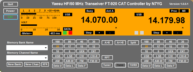
Getting Started: When the program is first launched, you will have a dark display. The PWR button will toggle the display on and off. If you are connected to the radio when you click the PWR button, it will automatically disconnect the serial port and return it to the computer for use by other programs. NOTE: The PWR button DOES NOT power and de-power the actual radio as there is no command set for that function as with other Yaesu models. Make sure the radio is ON and you have CAT enabled in the radios menu (for those radios that include that menu item).
Select the COM port from the selection box. This selection will remain persistent with each restart of the program until you change it. Select a poll rate from the selection box. These values are in milliseconds. Any value from 250 to 1500 can be selected. The ideal selection is between 250 and 750. At 250, the radio will be polled 4 time a second and will provide an almost real-time response for the display of the S-Meter. The downside: on slower computers, it may be difficulty interrogating mouse selections on the radios buttons and controls. If that is the case, increase the polling rate to find a happy medium. The rate you select will be stored and recalled on the next program restart. You will also find that faster polling rates will cause an increase in CPU use. The program author has found 750 ms to be an ideal value for my hardware and still get a good S-Meter response.
At the lower right of the meter display you will see a number such as 263 ms. This number represent the amount of time in milliseconds it takes to send the commands to the radio, get the data and process the data one time – poll cycle. Do not set you polling rate to anything less than the number you see here. Depending on you system you may see this number increase from time to time. This is normal and represents the threading processes that take place in a computer. My recommendation is to initially set your polling rate to 1000 ms and let the radio poll for a couple of minutes and get an idea what your average poll cycle is. Double the number and use that as a polling rate. In most installation I would expect your poll cycle to be less than 325 ms.
The CAT button will connect the program to the radio and start polling the radio for data and displaying it. The CAT button will illuminate green to let you know the radio is connected and polling. Clicking the CAT button again will stop all polling and disconnect the computer from the radio. If you find you need to adjust the polling rate, it can only be done in this disconnected state.
Radio Layout: The layout of the front panel is similar to the actual radio, but modified slightly to accommodate computer control. The A or Main VFO is to the right of the meter display and the B or Sub VFO is left of the right edge of the display. Each VFO displays the frequency to the nearest 10 Hz.
 The Step button will change the step range for use when incrementing or decrementing one of the frequency digits using the Up (+) or Down (-) buttons. Each click of the Step Button will increment the step range by one digit, up to the Mhz digit, then wrap around back to the 10Hz digit.
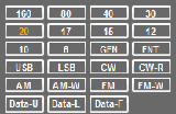 The Band and Mode button cluster is just like the radios button, but they have been grouped together. Clicking on one of the 11 band buttons will recall the last frequency and mode that was stored in the band register for that specific band. If you change a band, then the current frequency and mode prior to the band change will be stored in the band register for the previous band. It is similar in function to the band stacking register in your radio. The band that has been selected will be highlighted in orange on the face of the button. The GEN button is for General Coverage and will be illuminated for all frequencies that are outside of the 10 specific amateur bands. While 60 meters is now a legal amateur band, this radio was manufactured prior to that authorization so it will be considered in the General Coverage bands.
The ENT button will allow you to enter a frequency in MHz in the pop-up dialog.
The mode buttons are pretty much self explanatory and will change the mode of the VFO.
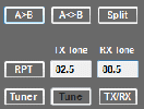 The miscellaneous button cluster between the two VFO's provides functions to set split mode of operations, swap the contents of the VFO's, copy VFO-A to VFOB, repeater operations, tuner operations and a button to manually togel the radio between transmit and receive. Split operations will set which ever VFO is selected to be the main VFO to the receiving VFO and the sub VFO as the transmit VFO. The VFO selections will be display with the green and red VFO indicators next to each VFO. The VFO with the green indicator is the receiving VFO and the red one will be the transmit VFO. The is no command structure to allow the computer to select which VFO is the main and which is the sub. Normally VFO-A is considered the Main and VFO-B will be the sub. To change that will require the operator to manually do that on the radio. Toggling the split button will then select the appropriate VFO for transmit and receive.
Repeater operations will be available if the VFO Frequency is greater than 29Mhz with a mode selection of FM. Clicking the repeater button once, will enable a minus (-) split. Clicking it again will enable a positive split (+) and clicking it again will disable repeater operations. The The repeater and split indication is just below the VFO-A display. There is no command to change the repeater offset frequency, so the user will have to accomplish that in the radios menu, one for VHF and another for HF.
Anytime repeater operations are enable, you will have an option to use CTCSS tones for transmit and receive if the repeater requires that and echos the tone back on the output. To change a tone frequency, double click the tone box and select the appropriate tone from the drop down listing. If you select the transmit tone to OFF, the receive tone will automatically be turned OFF and the box will become invisible. You must have a transmit tone selected for Tone Squelch to function. Refer to the 920 operators manual for further clarification on tone usage.
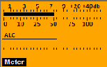 The meter display replicates the radio meter and provide some extra metering functions that are not available on the radio. The upper meter display either the receiving S units or the forward power output during transmit. The power meter is a multi-function meter and is selectable by clicking on the meter button. Each click of the button will cycle through the following functions:
- ALC – Automatic Level Control
- VOLT – The applied voltage from the power supply, measured in volts.
- AMP – The total current draw on the power supply and mesured in amperes.
- SWR – The standing wave ratio as internally computed from forward and reverse power.
- SHIFT – Currently non-functional.
- PITCH – The position of the CW keyer pitch control.
- SQL – The position of the squelch control.
- HPF – A relative indication of the DSP High Pass Filter.
- LPF – A relative indication of the DSP Low Pass Filter.
- NR – A relative indication of the amount of noise reduction.
- PROC – A relative indication of the amount of speech compression selected.
- DISC – The discriminator level when FM is selected
- RMC – An unknown function that even Yaesu is unable to explain.
Display Operations: The program uses something called a border-less form so the standard menu, decoration bar and form buttons are not visible. To get the floating menu to pop-up, right-click anywhere on the form and the menu will pop-out where you clicked. From this menu you can call up the help file, the About Box, minimize the program or exit. The Client Server item is currently disabled as that is a future function to be included at a later date. There is no item to maximize the display nor is there any method to resize the display as this would distort the display. To change the position of the display, simply hold down the left mouse button in the area between the power button and the caption at the top of the display and drag the display to your favorite position. The position will be recalled on the next restart.
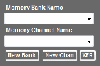
Memory Operations: Computer commands to manage the radios internal memories are poorly documented and do not function correctly on some series of radios. Therefore I decided to manage memories locally in a database. The total amount of memory storage is basically unlimited as all data is stored in an external database file. Instead of having one giant list of memory entries, we have identified a memory using a Memory Channel Name and a Memory Bank Name. There is no limit on the number of character you use to describe these so use something that is quite descriptive.
The Bank Name and Channel Name selections are standard Drop-Down boxes. The Bank name will be filled with all the bank names you have created. When selecting a Bank Name for the drop-down list, the Channel Name list will be filled with all the channel names that are assigned to a bank. Selecting a channel name from the list will transfer the stored data directly to the radio.
Before you start programming you memory channels, it is best to come up with a grouping strategy. For example, I use the radios General Coverage to listen to a number of Shot-wave stations around the world, so I have stored a number of frequencies for Radio Australia, Radio Japan, Voice of Russia and Radio Thailand. I used the name of the radio stations as the Bank Name, then a descriptive name for each channel.
Start by creating the Bank Names. Click the New Bank button and type in a bank name. Create all your Bank names at one time. Click the drop-down arrow for the bank names and all the name you just created are now in the list. To create a new memory channel, select the bank name the channel will be associated with. Tune the radio to the appropriate frequency and mode. You can also tune VFOB to a secondary frequency for that channel. Once you have the radio set, click the New Channel button and enter a descriptive name. The memory channel has now been stored and associated with a bank name. Continue doing this for the rest of the memory channels you wish to create for the selected bank name.
Switch bank names and complete the process for these memory channels. The XFR button will transfer the contents of the radio to the currently selected memory channel. You can use this to change the contents of a selected memory channel in the event you need to change a frequency or mode for that specific channel. Currently this is no method to delete a channel or a bank name. That is a future feature that I need to work out.
To recall a memory channel, simply select the bank name, then the channel name. Each time you select a new bank name, the channel name list will be refreshed with the matching channels.
The following variables are stored in the database for each memory Channel
- VFOA Frequency
- VFOA Mode
- VFOB Frequency
- VFOB Mode
- Repeater State
- TX Tone Frequency
- RX Tone Frequency
- Split State
- Tuner State
The database I use is a small, lightweight and self-contained Structured Query Language (SQL) server called SQLight. The data file that is stored can be found in your ProgramData folder. There are a number of third party programs that will allow you to manipulate these types of data files. If you elect to monkey with the file, you take a chance on corrupting your data as the data I store are enumerated values for everything with the exception of the frequency.