
IMD Primer
The following technical article on IMD is directly from the PSKCORE Technical Specification by Moe Wheatly AE4JY. Please read this very carefully. While there are many technical terms, most of this stuff should be recognizable by licensed hams. Noise can be a detrimental factor in computing IMD. This includes atmospheric noise along with any noise imposed due to incorrect antenna and feed line installations or improper grounding. Ground loops are HELL!!!!
3.2.11 IMD Measurement
One of the problems with PSK31 transmission is that most amateurs do not have the test equipment needed to measure the distortion in their transmitted signals. A spectrum analyzer is required to accurately measure the distortion products present in the transmitted signal. Currently one must rely on received signal reports to determine the quality of their signals. One method used is to calculate the IMD (Inter-Modulation Distortion) on the received signal. Although not the ideal way, this method can be useful if one is aware of the limitations to this method.
3.2.11.1 Measurement Method
One method of IMD measurement involves using two non-harmonically related tones to modulate the transmitter and observing the output for any spurious tones other than the two being used. If any non-linear amplification occurs in the transmitter, spurious frequencies will be generated that are combinations of the original tones and multiples of the sum and difference of the original tones.
If,
F1 = tone 1
F2 = tone 2
Then the following frequencies can be generated:
+/-nF1 +/- mF2 where n and m are integers.
The most common and strongest distortion product is called the third order product and is the frequencies of (2F1 – F2) and (2F2-F1).
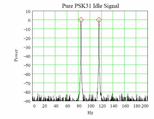
If one examines the PSK31 idle signal, it can be shown that the constant phase change of 180 degrees and the cosine shaped envelope of the signal generates two tones that are at the PSK31 center frequency +/- 15.625Hz. These tones can be used to measure the IMD of a transmitter. The following shows a PSK31 idle signal with a center frequency of 100Hz. The two tones are at 100+/- 15.625Hz or 84.375Hz and 115.625Hz.
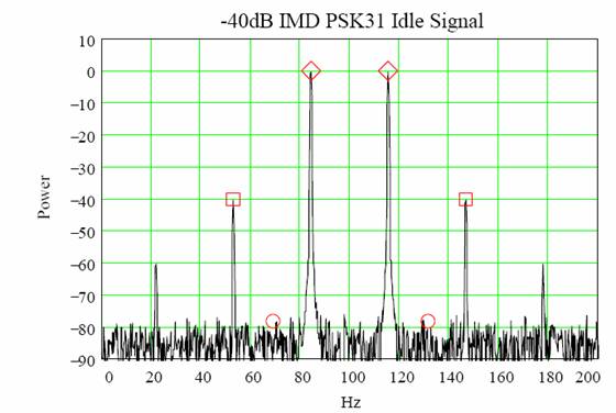
The third order product frequencies are (2F1 – F2) and (2F2-F1) or 53.125Hz and 146.875Hz. The following shows a PSK31 idle signal with some 3rd (and 5th) order IMD.
By measuring the power difference between the original tones and the 3rd order IMD tones, one can provide a measurement as to how much distortion is on the signal. In this case, the IMD is –40dB since the original tones are at 0dB and the 3rd order tones are at –40dB.
This works well with a strong received signal but look what happens if the signal is weak in the presence of noise.
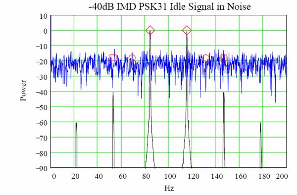
Note that if one measures the signal level at the 3rd order frequencies, then erroneous results are obtained because the noise level is higher than the distortion product. An IMD reading of –20dB will be obtained even thought the signal is actually –40dB.
This is why it is important that the received signal be well above the noise floor before trying to obtain an IMD reading. Another factor is the HF propagation effects that also introduce errors into this measurement method.
The PSKCore algorithm samples the original PSK31 idle tones, the 3rd order distortion tones, as well as the noise floor level. If the noise floor level is higher than the IMD tone then the IMD measurement is flagged as suspect. (See description of the MSG_IMDRDY message).
3.2.11.2 Goertzel Filter
The PSKCore dll uses Goertzel tone filters to sample the incoming signal and measure the IMD present. Goertzel filters are essentially IIR filters that calculate discrete Fourier transform frequencies. If a small number of frequencies are needed, this is much more efficient than calculating the entire FFT. These filters are commonly used in DTMF tone detection since only eight tones are required. Another advantage of the Goertzel algorithm is that only part of the filter needs to be calculated every sample time so a further savings is obtained.
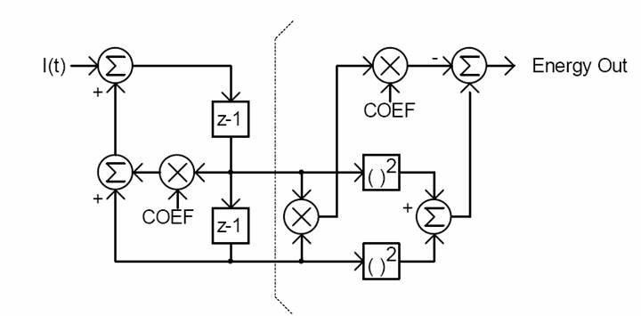
A block diagram of the modified Goertzel algorithm is shown below. The left side is calculated every sample time while the right side energy calculation only needs to be done every N samples where N is the Goertzel filter length. The constant "COEF" and value N determine the frequency and bandwidth of the tone detector.
COEF = 2cos(2pk/N) where k is the nearest integer that satisfies the equation:
k = N fi/fs where N is the filter length, fi is the desired filter frequency, and fs is the sample frequency.
For the PSKCore dll, the following parameters are used for the IMD measuring filters:
N = 288
fs = 500Hz
The signal is measured after the complex mixer so the signal center frequency is zero.
f0 = 15.625 Hz this is the PSK31 idle tone frequency
f1 = 31.25 Hz this is the frequency for measuring the noise floor
f2 = 46.875 Hz this is the 3rd order IMD frequency
k0 = Nf0/fS = 9 COEF_0 = 2cos(2pk0/N) = 1.96
k1 = Nf1/fS = 18 COEF_1 = 2cos(2pk1/N) = 1.8477
k2 = Nf2/fS = 27 COEF_2 = 2cos(2pk2/N) = 1.663
The basic algorithm is implemented as follows:
temp = I1;
I1 = I1*COEF-I2+samp;
I2 = temp;
if( ++NCount >= N )
{
NCount = 0;
Energy = I1*I1 + I2*I2 - I1*I2*COEF;
I1 = I2 = 0.0;
}
If a constant string of PSK31 idle symbols has been received then the following code is executed to calculate the IMD of the incoming signal:
//////////////////////////////////////////////////////////////////
// This routine calculates the energy in the frequency bands of
// carrier=F0(15.625), noise=F1(31.25), and
// 3rd order product=F2(46.875)
//////////////////////////////////////////////////////////////////
BOOL CCalcIMD::CalcIMDValue( INT &imdval)
{
m_Snr = 10.0*log10(m_Energy[0]/m_Energy[1]);
m_Imd = 10.0*log10(m_Energy[2]/m_Energy[0]);
imdval = (INT)m_Imd;
if( m_Snr > (-m_Imd+6) )
return TRUE;
else
return FALSE;
}