
PSK31, an RTTY Replacement?
By
Jeff Steinkamp, N7YG
(originally published in the 10-10 news in 2003)
Since its introduction in 1997, there has been a significant increase in PSK activity in amateur radio world, especially with the decreasing cost of the home computer and the fall of the sunspot cycle. Over the past year, many chapters began providing special certificates and awards for PSK contacts and there are now recommendations for a specific PSK category for QSO parties and contest. Unfortunately, many have seen the PSK31 acronym but have very little knowledge on the subject, thus the reason for this article – long overdue.
So, what is PSK31? PSK is the acronym for Phase Shift Keying and 31 is the bandwidth of 31 hertz. Now let us not fire off emails to the newsletter editor for lack in proofreading skills, 31 Hz is not a misprint. If this opportunity for narrow band communications has piqued you interest, please read on.
PSK31 Modulation Theory
The 31-baud BPSK (binary phase shift keying) modulation system used in PSK31 was introduced by SP9VRC in his SLOWBPSK program written for the Motorola DSP56002EVM and further developed by Peter Martinez, G3PLX. Instead of the traditional frequency-shift keying, the information is transmitted by patterns of polarity-reversals (sometimes called 180-degree phase shifts). This process can be thought of as equivalent to sending information by swapping-over the two wires to the antenna, although, of course, the keying is usually done back in the audio input into the transceiver. A well-designed PSK system will give better results than the conventional FSK systems that amateurs have been using for years, and is potentially capable of operation in much narrower bandwidths than FSK. The 31-baud data rate was chosen so that the system will just handle hand-sent typed text easily. There is a problem with PSK keying which does not show up with FSK, and that is the effect of key-clicks.
We can get away with hard FSK keying at moderate baud rates without generating too much splatter, but polarity reversals are equivalent to simultaneous switching-off of one transmitter and switching-on of another one in reverse phase: the result being key-clicks that are TWICE AS BAD as on-off keying, all other things being equal. Therefore, if we use computer logic to key a BPSK modulator such as an exclusive-or gate, at 31 baud, the emission would be extremely broad. In fact it would be about 3 times the baud rate wide at 10dB down, 5 times at 14dB down, 7 times at 17dB down, and so on (the square wave Fourier series in fact) The solution is to filter the output, or to shape the envelope amplitude of each bit which amounts to the same thing. In PSK31, a cosine shape is used.
To see what this does to the waveform and the spectrum, consider transmitting a sequence of continuous polarity-reversals at 31 baud. With cosine shaping, the envelope ends up looking like full-wave rectified 31Hz AC. This not only looks like a two-tone test signal, it IS a two-tone test signal, and the spectrum consists of two pure tones at +/-15Hz from the center, and no splatter. Like the two-tone and unlike FSK, however, if we pass this through a transmitter, we get inter-modulation products if it is not linear, so we DO need to be careful not to overdrive the audio. However, even the worst linear amplifiers will give third-order products of 25dB at +/-47Hz (3 times the baud rate wide) and fifth-order products of 35dB at +/-78Hz (5 times the baud rate wide), a considerable improvement over the hard-keying case. If we infinitely overdrive the linear, we are back to the same levels as the hard-keyed system.
There is a similar line of reasoning on the receive side. The equivalent to "hard-keying" on the receive side is a BPSK receiver which opens a gate at the start of a bit, collects and stores all the received signal and noise during the bit, and then "snaps" the gate shut at the end. This process gives rise to the receive-side equivalent of key-clicks, namely side lobes on the receiver pass-band. So, although this "integrate-and-dump" method is 100% efficient in the task of sorting out signal from noise, it will only reject signals by 10dB at 3 times the baud rate wide and so on, the same spurious rejection figures that we got as spurious emission figures for the transmit side. The PSK31 receiver overcomes this by filtering the receive signal, or by what amounts to the same thing, shaping the envelope of the received bit. The shape is more complex than the cosine shape used in the transmitter: if we used a cosine in the receiver, we end up with some signal from one received bit "spreading" into the next bit, an inevitable result of cascading two filters that are each already "spread" by one bit. The more complex shape in the receiver overcomes this by shaping 4 bits at a time and compensating for this inter-symbol interference, but the end result is a pass-band that is at least 64dB down at +/-31Hz and beyond, and doesn't introduce any inter-symbol-interference when receiving a cosine-shaped transmission.
Required Equipment
With the boring technical stuff behind us, what do I need to generate a PSK signal? If you own a personal computer with a sound card, you already have the main ingredients for a PSK station. Your selection of a sound card will determine your success at decoding PSK signals. Contrary to what computer manufactures want you to believe, not all sound cards are the same. While most are considered “Sound Blaster Compatible”, the operative word here is compatible. If your PC is equipped with an onboard sound chip such as the AC97 or similar, I do not recommend using this for PSK operations. While this sound implementation is good for playing your hacked music CD’s, it does not have the filtering required for good digital signal processing (DSP). Purchase and install a good quality PCI sound card. Any good motherboard will support multiple sound cards and dedicating one sound card for ham radio and another for the windows sound system just makes sense.
Interface and Hook-up
Figure 1.
Figure 1 above illustrates the recommend connections between the radio and the computers sound card. The interface unit can be any of the commercially available units on the market or a home brew unit. While construction of an interface unit is beyond the scope of this article, there is a multitude of information available on the internet to construct these units and many are specific for a particular manufacture of radio. The premise behind the interface unit is to provide the necessary isolation between the output of the sound card and the input of the radio.
The RTS or DTR line from a specific serial port normally provides transmitter keying. These low current (10ma max) data lines are not designed to handle the keying requirements of many of today radios, especially some of the older tube type radios. Therefore, some form of isolation is required. Likewise, connecting the sound card output directly to the microphone input is just asking for impendence mismatching problems and ground loops. Appendix 1 provides a list of manufactures of commercial interface units. Check your software’s help file as many include various different circuits for interfacing.
Software
This article is based on the software implementation of PSK31. There are hardware alternatives that are on the market. I have no experience with these products so I cannot comment, but Kantraoics has just released their KAM XL that includes PSK31. The Tucson Amateur Packet Radio Association has an excellent primer on hardware DSP with links to sites that offer information on hardware DSP kits.
Peter Martinez, G3PLX, wrote the original Windows software implementation and that program is still available today, although not widely used. The main players in the Windows software arena are Mixw, DigiPan, and WinPSK (refer to appendix 2 for a list of all available PSK31 software). Software is also available for the Linux and Mac platforms. I have used the Linux products and while their graphical interfaces are not as robust as the Windows version, they do an excellent job of decoding PSK signals.
The majority of the windows software is wrapped around the PSKCORE.DLL written by Moe Wheatly, AE4JY. Moe has an extremely informative Technical Specification available in PDF format on his web site (http://www.qsl.net/ae4jy). The DLL application performs all the necessary DSP processing and provides the calling software with the decoded data along with various messages on signal strength, amplitude data for spectrum displays along with other software control messages. Any programmer with a basic understanding of calling subroutines from a DLL file can write their own software package in a matter of minutes. As I write this article, I am in the testing phase of a new product called YGPSK that should be available for download (http://home.earthlink.net/~n7yg) as you read this.
Installation of any of these software packages is a matter of simply executing the supplied installation program. Unless you are computer whiz, I recommend using the default folders setup by the programs author. I have run across programs that assume you are installing them in the recommend folders and will not function correctly when installed on different drives or folders (poor programming practices!). Once you have the software installed, read all the included help files and README files that are included with your software. They will inform you about all the unique program features, specific setup requirements, and program functionality.
One item these help file miss is the Sound Card Sample Rate. On older Win9.x systems, there was a specific setup for the sample rate and could normally be found with the driver software. If you are running the older Win OS, you will need to set this for the highest rate possible, at least 11025 KHz. This setting can be found in many of the older PSK software setup routines. All the new software will use the Sample Rate Conversion Quality setting in the Sound Card and Audio Devices found in the Windows Control Panel. Set this to the highest setting available. This will ensure the best quality conversion. There is a price you pay for this increased quality - more system resource usage. Therefore, it is recommend you use the faster computer you can lay your hands on, load it up with memory and disable any screen savers.
Setting up the software to key the PTT line is an extremely important setting. All the programs I have used provide this function via the DTR and RTS data line using one of the available serial ports. Make sure you select the correct COM port and keying line if using an interface unit. Most interface units will use either line. VOX is an option but,. the VOX circuits in all the current production radios are tailored for the human voice and function poorly with the high frequency tones generated by the sound card. This statement is based on reports I’ve had from other PSK users in the past. With that said, I have used VOX on my FT-920 with out any noticeable problems other than finding the gain setting in the multitude of buried menus in the radio.
If you are feeding your tones in via the microphone connector or an auxiliary microphone connector, make sure you do not have the microphone active when the transmitter keys. Ambient room noise picked up by a microphone will cause untold distortion on your transmitted signal. Turn off any speech processing circuits and audio compressors as they also create unwanted distortion. This will also hold true if you are using the phone patch inputs that are provided on some of today’s radios. The best place to interface your radio with the computer is using the DATA accessory jack that is provided on most of the newer radios. Please refer to your manual to locate what pins/signals are provided and the proper method to interfacing.
Tuning and Receiving a PSK31 Signal
The hardware is connected, the software is installed and running, now what? Locating and tuning a signal is actually quite simple with the controls provided in most software. Tune the radio to the 20-meter PSK frequency (14.070 MHz) and observe the waterfall. You should see a green (or blue) speckled background as the waterfall ‘paints’ its display. The speckled pixels represent the background noise. You may also see some higher intensity vertical line similar to a set of railroad tracks. This is a PSK signal. Figure 2 is a screen shot of a waterfall display with a number of signals across the selected bandwidth. The vertical white line is the tuning indicator
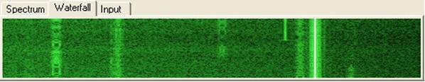
Figure 2
and can be placed anywhere in the waterfall display simply by placing the mouse over a signal and clicking with the left mouse button. If you have captured a PSK signal, you will immediately see the decode characters in the terminal window. This screenshot shows six PSK signals of different amplitudes and one constant carrier tone. The trace just to the right of the captured signal is an extremely weak PSK signal, but I was able to maintain an 80% copy on this station. If your display does not look similar to Figure 2, then you will need to adjust the incoming audio level in the Windows Volume Control and Audio Mixer Panel. Most software I have used provides a hook to this program somewhere in the menu structure. Adjust the Line IN or Mic In level controls to achieve a good contrast difference between the noise level and the brightness of the PSK signals. If you adjust the level too high, you will ‘flood’ the display with noise. If you adjust the control too low then the display will become black. If you are using speaker audio from the radio, be very careful that you DO NOT overdrive the sound card input. If you do, you will damage the sound card input circuits. I have a number of these sound cards laying around with unusable inputs just for the asking!!!
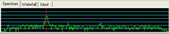
Figure 3
Figure 3 is a screen shot of a signal in the spectrum display. This display will show the relative amplitude of each frequency step across the selected bandwidth. Although it may not be evident with this screen shot, there is a slight amplitude dip between the two signal peaks. This is the sign of a properly tuned transmitter. Using the Waterfall Display and the Spectrum display, you can quickly identify and tune a PSK signal. In this Spectrum display, you will also notice the level of the noise floor of your radio.
Transmitting PSK
Setting up your transmitter is a little more challenging than receiving. The main thrust to write this article was the number of poor quality PSK signal I have observed on the bands over the years. When transmitting a PSK signal you are subjecting your transmitter to 100% duty cycle similar to RTTY, FSK, or SSTV. Blow the dust off the equipments owners manual and familiarize yourself with the manufactures limits for 100% duty cycle transmissions. You might be surprised to discover your 120-watt radio is rated at 40 watts 100% duty cycle for a specific time duration. Armed with these limitations we can now set the software for transmission.
The audio output level will require the adjustment of the radios RF power control, mic gain control, the audio mixer volume slider and the wave slider. These setting will differ depending on your individual equipment, so experiment to get the best quality signal. Start with the RF power control at the maximum setting and the mic gain around the nine o’clock position. The volume and wave sliders will affect each other depending on where you are taking the output from the sound card. Set your radios meters to show output power and ALC. Active the software’s transmit function to send an idle tone. Adjust the controls so you are not exceeding the manufactures power limitations and you have no noticeable ALC action. If you have a friend who can listen to your signal locally, this is the best method to determine if the signal is clean.
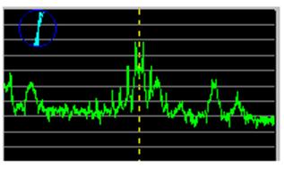
Figure 4
Figure 4 is a good example of an overdriven PSK signal. Notice the distortion on either side of the signal peaks. This signal was accompanied with an IMD reading of -12 dB. Strive for an IMD reading on the other end of something less than -25. IMD reading are only computed during idle time of the PSK signal and my not always be display on your software.
Making the Contact
The first contact is always the most difficult especially when using software you are not familiar with. Search the band for a CQ and answer by activating the transmit function and typing your text into the transmit buffer window. Everything you type will be echoed into the receive buffer window. If you have the transmitter setup correctly, then the other station should hear you depending on conditions. Remember when you are finished typing to return the software to the receive mode. You could try a CQ. Locate an unused slice of spectrum and click the mouse in the spectrum or waterfall display to set the receive and transmit frequencies. Activate the transmit function and type your CQ message. Alternatively, if you have a pre-defined CQ macro, click that button and you CQ will be sent.
Macros and Brag Files
Every PSK31 software package I have used to date, including my entry into the software market has a facility for macros. Macros are used to define bits of information that is used repeatitly Most software packages have a primitive editing package that will allow you to edit the text for each macro. Some programs will require you to edit a special macros file. In either case, refer to the software’s help manual for procedure on using and setting up the macros.
Brag tapes (Brag files) date themselves to the Model 15 and Model 35 KSR era. Basically, these were small lengths of paper tape the operator made that include the information on the station setup and some personal information about the operator. The tape was then inserted into the tape reader and the content of the tape was transmitted. Today, a brag file is simply a small text file stored on the computers disk drive. PSK is 100% duty cycle so keep the bragging rights to a minimum. A 10 minutes dissertation on the architectural construction of the swimming pool will be better handled using that new Web Cam the XYL gave you for Christmas.
Summary
PSK is an excellent weak signal mode of digital communications that requires nothing more than the computers soundcard and an external interface unit. The extremely poor band conditions for the 2003 Winter QSO party is indication of the decline on the solar cycle and will be the ‘acid test’ for PSK over the next few years. Voice communications will become difficult on 10 meters as many of us who have experienced a few previous cycles will attest. We now have the opportunity to keep 10 meters rolling and pickup some new 10-10 numbers. ‘Lets Roll!’
|
Software Name |
Website |
|
PSK Express |
|
|
WinPSK |
|
|
Mix32 |
|
|
WinPSKse |
Does not appear to be available as of June 2006 |
|
PSK31SB |
|
|
Zakanaka |
Does not appear to be available as of June 2006 |
|
Digipan |
|
|
WinWarbler |
|
|
Multi-Mode (MAC) |
Table – 1 Available PSK31 Software